


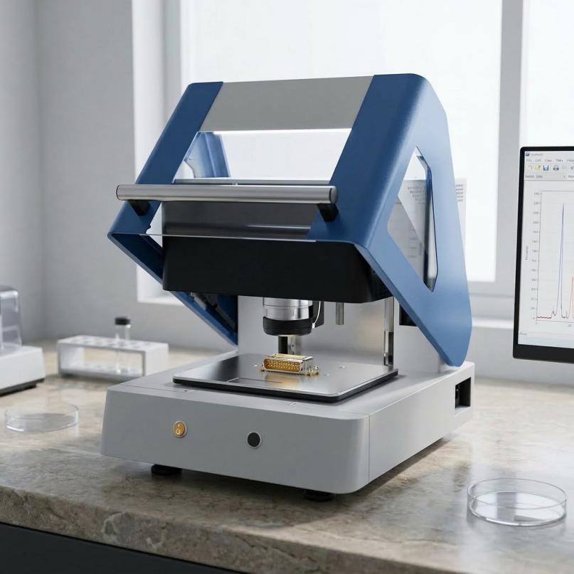
XRF coating thickness measurement is used to determine the thickness of a coating. You’ll find it in plating QC, electronic component tests, precision part analysis. No cut, no probe marks. When the material mix and arrangement is suitable, XRF tests the part without damage.
But to detect an element is one thing. Another is obtaining accurate coating thickness. Coating and substrate makeup, layer stack, calibration, measuring site, all of these can move the number. Learn them and you can know if XRF is a good choice for your sample and what type of coating thickness analyzer you require.
Alt
How Does XRF Measure Coating Thickness?
XRF does not use a probe to assess physical height. It fires x-rays, reads the fluorescence coming back, then uses calibration or a math model to measure thickness. Three main parts.
1. X-ray Excitation
X-ray Excitation The equipment bombards the sample with primary x-rays. Atoms get excited. Some give off characteristic luminous X-rays. Every element has a unique fingerprint, so the instrument can tell what it is looking at. This is the same way elemental analysis is done by X-ray fluorescence spectroscopy.
Take bits of metal. The signal tells you what components are present. But for the coating thickness, the software also has to differentiate between what’s coming from the coating and what’s coming from the substrate.
2. Fluorescence Signal Detection
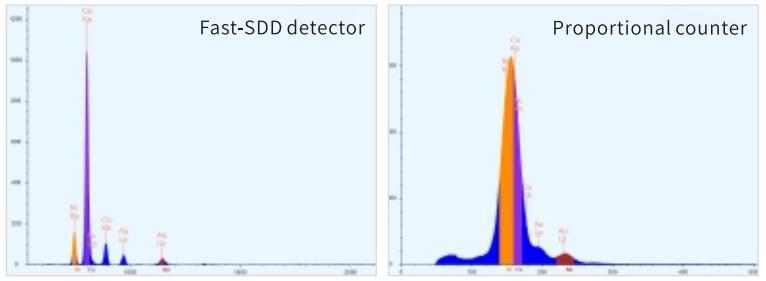
Fluorescence Signal Detection: The detector picks up the fluorescence. It looks at energy and intensity. For coating thickness, signals from coating elements and substrate elements—and how they shift—tell you about layer structure and thickness.
Change the coating thickness, and the coating/substrate signal ratio may change. But not the same way for every material combo. One signal intensity won’t cover every coating.
3. Thickness Calculation
The software combines the signal, coating and substrate info, calibration data or analytical model. Then it calculates coating thickness. Some systems can handle multilayer thickness or composition at the same time—if the conditions are right.
ASTM B568, the standard test method for measurement of coating thickness by X-ray spectrometry, measures coating mass per unit area. Know the density and other needed conditions? You can convert that to linear thickness.
So XRF thickness measurement isn’t just about the box. Material info and method matter. Two parts can look the same. Different coating, substrate, or layer stack? Don’t assume the same settings will work.
Which Coatings Can XRF Measure?
XRF coating thickness measurement is common in metal finishing and precision electronics. But suitability depends on coating material, substrate, thickness, and what the instrument can analyze. Look at the actual coating/substrate combo first. The coating name alone won’t tell you much.
Metal Plating
Gold, nickel, tin, copper are the usual suspects for XRF thickness measurement. How well they work, depends on the material mix and equipment arrangement.
In plating, thickness can drive wear resistance, corrosion resistance, conductivity, appearance. Check it, and manufacturers can see if the process meets spec and spot differences between parts or spots.
But capability for one metal coating doesn’t transfer to another. Elements in coating and substrate, thickness range, fluorescence signals—all can change the analytical conditions.
Multilayer Coatings
Some XRF thickness systems handle multilayer coatings. Electronic parts often use several metal layers for electrical, protective, or surface treatment needs.
These samples are harder. Signals from different layers can affect each other. The instrument needs multilayer analysis capability. The method has to fit the real material combo.
Need multilayer measurement? Confirm the instrument can identify the target layer structure. Don’t trust “multi-element analysis” on a spec sheet to mean each layer can be measured separately.
Common Industrial Applications
XRF coating thickness measurement shows up in:
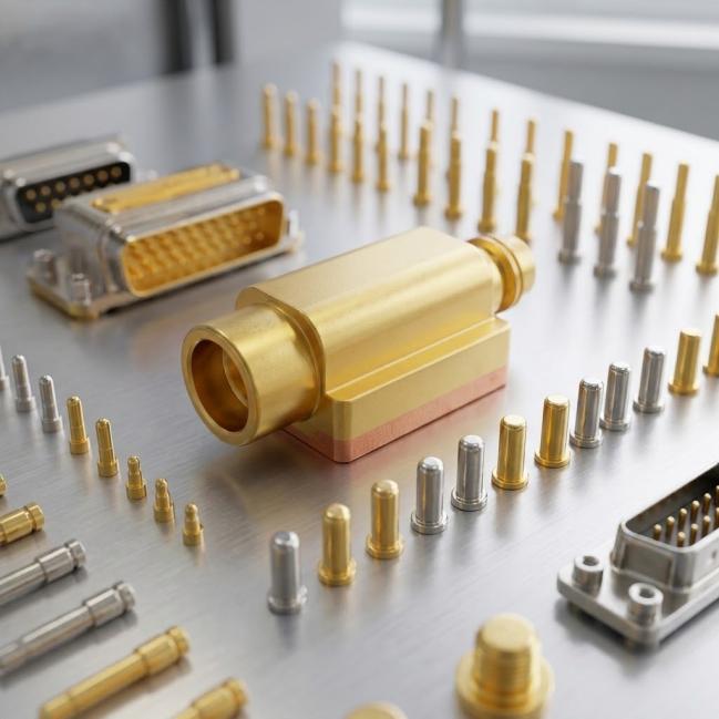
PCB and electronic components: surface treatment layers on boards, coatings on precision electronic parts.
Electrical connectors, metal coatings in contact regions – to help in the assessment of process repeatability.
Electroplated work pieces: check coating thickness to production or quality acceptance criteria.
Precision metal parts: Measure coating thickness at specified points, and reduce destructive sampling.
One caveat: XRF is not suitable for all coatings. Paint, powder coatings, other organic layers. Not only metal plating processes. It is reliant upon the coating composition, substrate and the measuring to be done. Sometimes another thickness approach is the better call.
How to Measure Coating Thickness by XRF
When using XRF to measure coating thickness it is not enough merely to load the part and read the screen. Utilize the statistics, authenticate the sample data, pick the procedure, and then evaluate the stability.
Step 1: Verify the Coating and Substrate
Confirm composition of coating and substrate. If possible find out the number of layers and the approximate thickness range.
That info informs the analytical approach. Unknown material combination? Other than calibrating target? The outcome can differ.
For multilayer coatings, determine if you need the overall thickness or each layer individually.
Step 2: Select the Appropriate Measurement Method
Match the substrate/coating mix to a manner that the instrument supports. Select the suitable calibration curve, reference standard or analytical model.
Any thickness acceptability criterion for production? Check Verify technique for thickness range and QC requirements. Strict enforcement? Build measurement and verification to the relevant standard.
Step 3: Position the Sample Correctly
Put the target area in the instrument’s effective measurement position. Focus and position it the way the equipment requires.
Small parts make this critical. Tiny measurement spot? A small offset can make the inspected area miss the target. Curved surfaces, grooves, threads, irregular shapes—they can all affect positioning and measurement conditions.
Step 4: Measure and Repeat
Run the measurement. Repeat at multiple positions as quality control requires.
One measurement reflects one spot. It may not represent the whole part. Need coating uniformity? Plan measurement points around the part structure and acceptance requirements.
Step 5: Review the Results
Compare results with product specs, process requirements, or applicable reference standards. Numbers fluctuating? Clearly off? Check material info, calibration, sample positioning, measurement conditions. Don’t reject the workpiece right away.
For critical QC, use applicable reference standards or another verified method to confirm the result reflects reality.
What Affects XRF Coating Thickness Measurement Accuracy?
XRF thickness results can be altered in a number of ways. Know them and you can make smarter choices for gear – and troubleshoot when the figures appear funny.
Coating and Substrate Composition
Coating and substrate elements affect the fluorescence signal and analysis. The use of different materials might produce diverse signal responses. Calibration must correspond to the target sample.
Does the real composition not fit analytical set-up? The equipment may be able to detect the elements, but the thickness can still be unreliable.
Coating Thickness and Layer Structure
The change in thickness affects the signal. But the reaction of the instrument is not the same in all ranges. If you extend beyond the useful measurement range for particular material combo, the signal may not resolve minor variations in thickness.
Multilayer coatings add signal contributions from each layer. Equipment or analytical model doesn’t support the target layer structure? Longer measurement time won’t fix it.
Calibration and Reference Standards
Calibration must fit the material and thickness range. Composition, thickness, and condition of reference standards affect how useful they are as a reference.
Long-term production QC? Set up calibration check procedures. Record measurement conditions and result changes. That tells you whether results stay stable—not just whether one reading looks good.
Measurement Spot and Positioning
Measurement spot size affects whether the instrument hits the target. PCBs, connectors, tiny parts—small measurement points mean any offset between spot and target can change the result.
Choosing equipment? Don’t just look at thickness capability. Check measurement spot, focusing method, positioning capability against workpiece size.
Surface Geometry and Repeatability
Flat samples position easily. Curved, grooved, stepped, irregular parts? Harder. Sample doesn’t match the instrument’s measurement position? Positioning isn’t consistent between runs? Results can fluctuate. Surface condition and preparation can affect some XRF analyses. Set appropriate XRF sample preparation requirements for the task.
Unstable results? Check workpiece position, focus, measurement point consistency. Then check calibration and material settings. For common positioning and calibration issues in coating thickness measurement, XRF coating thickness measurement technical guide also covers how these factors affect results.
How to Choose an XRF Coating Thickness Analyzer
Don’t pick an XRF coating thickness analyzer by speed or advertised precision alone. Fit matters more. Can it handle your actual samples? Does it meet daily inspection and QC needs?
Check Material Compatibility and Thickness Range
Pin down coating, substrate, layer count, expected thickness range. Then confirm the instrument supports the analytical method.
Multilayer coatings? Check multilayer analysis capability. Narrow thickness range or strict specs? Look at actual measurement performance for the target material combo.
Match the Measurement Area to the Sample
Regular-sized workpieces: confirm the measurement area covers the target. PCBs, connectors, tiny parts: micro-area measurement capability deserves extra attention.
Curved surfaces, grooves, special features? Check positioning, focusing, sample movement methods against those shapes.
Consider Calibration and Repeatability
Equipment should work with applicable calibration methods. It should meet repeatable measurement needs in production or lab. Don’t judge from one precision number. Performance can vary with material and thickness.
Before buying, prepare representative samples. Confirm the instrument covers the required measurement area, material combo, and thickness range.
When Micro-area Measurement Is Required
Tiny areas, precision electronic parts, irregular workpieces—positioning method and stage design matter a lot.
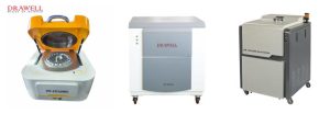
For example, Drawell’s micro-area XRF coating thickness analyzer—EDX2000A automatic micro-area coating thickness analyzer comes with an automatic XYZ three-dimensional moving stage and a dual-laser positioning system. It can position and analyze coating thickness on flat, concave-convex, edged, and curved surfaces.

These design choices target micro-area coating thickness needs. Still, whether a specific sample can be measured, the thickness range, and real performance depend on coating, substrate, sample structure, and equipment analytical conditions. Clear quality acceptance requirements? Test actual samples before purchase.
Final Thoughts
XRF coating thickness measurement gives you a non-contact, non-destructive way to measure applicable metal coatings and some other coatings. It fits plating, electronic components, precision parts QC especially well.
But the instrument isn’t the whole story. Coating/substrate combo, layer structure, calibration method, sample positioning—all affect results. Selecting a system? Clarify what to measure, which area, what thickness range. Then confirm the instrument has the matching analytical capability.
Tiny areas or complex shapes? Evaluate positioning and focusing design alongside measurement capability. Match those requirements to real samples. That’s the practical way to choose a suitable XRF coating thickness measurement system.
Get Quote Here!
Latest Posts



What Next?
For more information, or to arrange an equipment demonstration, please visit our dedicated Product Homepage or contact one of our Product Managers.


