


If a coating is too thin by a few microns, it may not meet the requirements of corrosion resistance. If the coating is too thick, it can squander costly materials such as gold, silver or tin. So plating shops, electronics manufacturers and QC labs all need a quick way to check thickness without damaging individual parts.
One of the most prevalent techniques to achieve that is XRF coating thickness measuring. It is non-destructive and normally takes seconds each reading. This guide discusses the principles of X-ray fluorescence thickness measurement, factors influencing the accuracy of XRF thickness measurement, strategies to achieve more accurate results and limitations of the technology.

How XRF Measures Coating Thickness
The XRF analyzer shines X-ray beam upon the part. The beam ejects inner-shell electrons of the coating atoms and of the substrate atoms. Electrons from higher orbitals fall to fill the vacancy and give off X-rays with an energy characteristic of the element. This secondary emission is a fingerprint for each element. It’s the fluorescent in the name.
Thickness is determined from signal strength. Generally, with increasing coating layer thickness, the fluorescence signal from the coating increases, whilst the fluorescence signal from the underlying substrate is more reduced.
The analyzer does not read thickness directly. The detector counts x-rays and the program compares the counts with calibration data from reference standards or a fundamental parameters model. Then it reports a thickness value.
ISO 3497 XRF coating thickness measurement is described by mass per unit area. If the coating density is known the result can be translated to a linear thickness. Some XRF systems can measure multilayer coatings. These include devices configured to measure up to three layers, depending on the coating structure and the analytical approach used.
What Can Affect XRF Thickness Readings
In practice, if you get a weird readout, it’s almost always a setup problem, not the instrument. Knowing the typical explanations helps a lot in finding the problem. The most important ones are summarized in the table below.
| Factor | How it affects the result |
| Coating and substrate materials | Element composition and substrate signals affect the calculation. |
| Coating thickness | Very thin or very thick layers may require suitable measurement conditions and calibration. |
| Surface shape and condition | Curved, rough, or uneven surfaces can affect measurement geometry. |
| Measurement spot | A small test area may not represent the entire coated part. |
| Calibration and standards | An unsuitable calibration can introduce systematic errors. |
Of these, calibration is the one we would check first. A properly placed sample will nonetheless yield a biased figure if the calibration is not representative of the true coating system.
Steps to Improve XRF Measurement Accuracy
You get consistent outcomes from a constant process, not from a single setting. Most of it is covered by five steps:
- Identify the coating structure. See what layers exist and in what sequence. For example, a nickel underlayer is deposited differently than gold on copper.
- Choose a suitable calibration. Use standards that mimic the actual coating and substrate material to calibrate the analyzer.
- Position the sample carefully. The area of measurement needs to be flat, stable and at the same distance every time.
- Repeat the measurement. Get some readings across the portion. Look at the spread, not just one figure.
- Check against a reference method when needed. A useful cross-check is cross-sectional measurement under a microscope, especially when validating a new product or measurement method.

When Is XRF Suitable for Measuring Coating Thickness
XRF is quite good for many metal coatings but NOT the only answer. The suitability of XRF depends on the coating, the substrate material and the geometry of the part. Here’s the table of where do you look:
| Application or measurement condition | Key consideration |
| Single-layer metal coatings | Generally suitable when the coating and substrate can be distinguished and the analyzer is properly calibrated. |
| Multilayer coatings | Measuring individual layers requires an analyzer and method capable of distinguishing the layers, supported by suitable calibration or modeling. |
| Very thin coatings | Measurement capability depends on the coating and substrate materials, instrument configuration, and measurement conditions. |
| Small or curved components | Small measurement areas and curved or uneven surfaces can affect positioning and measurement geometry. |
According to ISO 3497, the practical measurement range also depends on the energy of the fluorescence being analyzed and on the measurement uncertainty you are prepared to accept. Thus, there is no one thickness restriction for all coatings. It is worth evaluating a few typical samples before agreeing on a method.

Choosing an XRF Analyzer for Your Coating Application
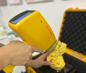
When measuring coating thickness using XRF, the fluorescent X-rays emitted by the coating and substrate are analyzed and used to calculate the thickness based on calibration data. And the measurement of metal coating thickness is only as good as the match between the analyzer, the calibration and the part. You should select an XRF coating thickness analyzer based on material combination, number of layers, thickness range and size of the component.
That’s the kind of question we work on with labs and manufacturers at Drawell. If you are comparing options or are unsure whether XRF is suitable for your coatings, share the details of your samples and we can help you find a suitable configuration.
Get Quote Here!
Latest Posts

What Next?
For more information, or to arrange an equipment demonstration, please visit our dedicated Product Homepage or contact one of our Product Managers.


