

X-ray Diffraction (XRD) is a powerful analytical technique used to reveal the atomic and molecular structure of materials. Its versatility makes it indispensable for characterizing both highly ordered crystalline solids and disordered amorphous substances. In polymer science, XRD provides critical insights into the arrangement of polymer chains, allowing researchers to quantify crystallinity, identify crystal structures, and understand the impact of processing on material properties. This article will detail the specific considerations required when applying XRD to crystalline and amorphous polymers, highlighting key differences, common challenges, and practical solutions.

Basics of XRD for Polymer Analysis
The fundamental principle of XRD relies on the elastic scattering of X-rays by electrons within a material. When X-rays with a specific wavelength (λ) interact with a sample, they are diffracted in various directions.
Principle of X-ray diffraction in identifying atomic/molecular arrangements: For diffraction to occur, the atoms or molecules within the material must be arranged in a somewhat periodic manner. Each atom scatters X-rays, and if these scattered waves are in phase, they constructively interfere, resulting in a detectable diffraction signal. The angles (2θ) at which these signals appear are characteristic of the material’s atomic arrangement.
Bragg’s Law (nλ = 2d sinθ) relates the X-ray wavelength (λ), diffraction angle (θ), and interplanar spacing (d) to determine structural parameters. It is foundational in interpreting XRD data for both crystalline and semi-crystalline polymers.
Diffraction in Crystalline vs. Amorphous Materials
The most striking difference in XRD patterns lies in the presence or absence of sharp, distinct peaks:
- Crystalline Materials: In crystalline materials, atoms are arranged in a highly ordered, repeating three-dimensional lattice. This long-range order leads to strong constructive interference at specific 2θ angles, resulting in sharp, intense diffraction peaks. Each peak corresponds to a specific set of crystal planes (hkl) with a unique d-spacing. For example, a perfectly crystalline silicon wafer would show very sharp, well-defined peaks.
- Amorphous Materials: Amorphous materials, conversely, lack long-range atomic order. Their atoms or molecules are randomly arranged or possess only short-range order. Consequently, X-rays scattered by these materials do not undergo significant constructive interference over long distances. Their XRD patterns therefore exhibit broad, diffuse “halos” or “amorphous humps” rather than sharp peaks. The position of the maximum of these broad features reflects the average nearest-neighbor distances within the short-range ordered domains. A good example is soda-lime glass, which displays a characteristic broad hump.
In the context of polymers, many are semi-crystalline, meaning they possess both crystalline and amorphous regions. Their XRD patterns are a superposition of sharp crystalline peaks and a broad amorphous halo, reflecting this dual nature. Understanding how to interpret both aspects is crucial for comprehensive polymer characterization.
Difference Between XRD for Amorphous and Crystalline Polymer Phases
Polymers can exhibit crystalline, amorphous, or semi-crystalline structures. Each of these phases responds differently in XRD analysis due to the way polymer chains are organized. Understanding the unique XRD signatures of each phase helps researchers identify structural characteristics and changes during processing or treatment.

XRD for Crystalline Polymers
Crystalline polymers contain regions where polymer chains are packed in a regular, repeating pattern, forming crystallites. These ordered structures produce distinct features in XRD patterns:
- Identification of Crystalline Peaks
Sharp, well-defined diffraction peaks appear at specific 2θ angles. These peaks correspond to reflections from planes in the crystal lattice. The presence and position of these peaks help identify the crystalline phase and material type. For example, Polyethylene (PE) shows major peaks at ~21.5° and 23.8°.
- Calculation of Crystallinity Index
Crystallinity index indicates the percentage of crystalline content in a semi-crystalline material. It is typically calculated from the ratio of the area under crystalline peaks to the total scattering area (crystalline + amorphous). A higher index suggests greater rigidity and higher thermal resistance.
- Determination of Unit Cell Parameters
From the position and shape of diffraction peaks, unit cell dimensions (lengths a, b, c and angles α, β, γ) can be calculated using indexing software. This helps determine how polymer chains are arranged in three-dimensional space.
- Use Cases
Common examples of crystalline polymers and their characteristic peaks:
| Polymer Type | Major XRD Peaks (2θ) | Notes |
| Polyethylene (PE) | ~21.5°, ~23.8° | Orthorhombic lattice |
| Nylon-6 | ~20.3° | α-form crystals |
| PET | 16.5°, 22.5°, 25.5° | Indicates semi-crystalline nature |

XRD for Amorphous Materials
Amorphous polymers lack a regular internal structure, resulting in broader, less distinct features in XRD patterns.
- Broad Humps Instead of Sharp Peaks
In place of sharp Bragg peaks, amorphous materials display a wide, low-intensity hump—often called a “halo”—which arises from short-range molecular order. For example, Amorphous PET shows a halo centered around 22°–24°.
- Use of Halo Pattern to Estimate Short-Range Order
The center and width of the halo can provide clues about average atomic distances and the degree of local ordering. A narrower hump may indicate more structured packing even in the absence of crystallinity.
- Application in Detecting Changes During Thermal or Mechanical Treatment
Heating, drawing, or quenching may induce partial crystallization or rearrangement. These changes can be tracked by observing the appearance of new peaks or shifts in the halo. For example: Annealed amorphous PLA may show emerging crystalline peaks over time.

Special Insights: XRD for Graphene Oxide
Graphene oxide (GO), a layered nanomaterial with oxygen-containing functional groups, exhibits distinct diffraction behavior and offers valuable insights when incorporated into polymer matrices.
- Structural Analysis of Graphene Oxide and Its Exfoliation State
Pristine GO typically shows a strong (001) peak around 10° 2θ, corresponding to an interlayer spacing of ~0.8 nm. A reduced or disappeared peak suggests exfoliation or thermal reduction. For example, after chemical reduction, the 10° peak weakens or shifts, indicating removal of oxygen groups and restacking of layers.
- Interlayer Spacing Changes Upon Functionalization
When GO is functionalized or interacts with polymer chains, interlayer spacing may increase due to molecule insertion, resulting in a peak shift to lower angles. This is useful in assessing the extent of polymer intercalation or bonding.
- Use in Polymer Matrix Composites
In nanocomposites like PVA/GO or PU/GO, uniform dispersion of GO sheets leads to diminished or vanished (001) peaks, indicating good exfoliation. This typically correlates with improved mechanical and barrier properties of the composite.
| Material Type | Key XRD Feature | Structural Insight |
| Pristine GO | (001) peak at ~10° | Layered structure with interlayer water |
| Reduced GO | Peak disappears or shifts | Exfoliation or removal of functional groups |
| GO in composites | Broad/no peaks | Good dispersion in polymer matrix |
Summary Table: XRD Comparison of Polymer Phases and GO
| Characteristic | Crystalline Polymers | Amorphous Polymers | Graphene Oxide |
| XRD Pattern | Sharp Bragg peaks | Broad halo (diffuse scattering) | Sharp (001) peak at ~10° (pristine GO) |
| Structural Order | Long-range order | Short-range order only | Layered 2D structure |
| Crystallinity Measurement | Possible (via peak area analysis) | Not applicable | Not measured by crystallinity index |
| Effect of Processing | Peak intensity and position change | Halo width/position change | Peak shift or loss due to exfoliation |
| Application Insight | Predicts strength, thermal behavior | Monitors densification or relaxation | Indicates dispersion in composites |
Common Challenges and Solutions in Polymer XRD
Working with polymers in XRD presents unique challenges due to their inherent structural complexity, including semi-crystallinity, flexibility, and processing-induced anisotropies. Addressing these challenges is critical for obtaining reliable data.
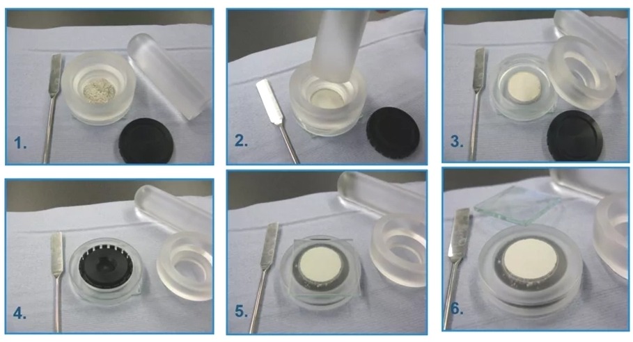
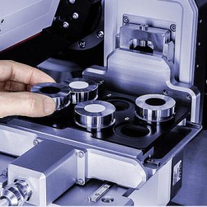
Challenge 1: Sample preparation for amorphous vs. crystalline:
Proper sample preparation is paramount, as it directly impacts the quality and interpretability of the XRD pattern. Polymers can be soft, sticky, or difficult to grind into fine, homogeneously packed powders, which is ideal for achieving random orientation of crystallites. For films, surface roughness can lead to signal absorption and baseline issues.
Solutions:
- Crystalline Powders: For quantitative crystallinity analysis, finely grinding the polymer (e.g., using a cryogenic grinder for tough polymers) helps create small crystallites that are randomly oriented in the sample holder. Pressing the powder into a pellet or using a specialized sample holder (e.g., front-loading) can improve packing density and surface flatness.
- Films/Bulk Samples: For films or solid pieces, ensuring a flat, smooth surface is essential. Techniques like hot-pressing can create suitable films. If studying preferred orientation, the sample must be mounted consistently relative to the X-ray beam. When analyzing amorphous samples, careful preparation to avoid any induced crystallization during handling (e.g., excessive pressure or heat) is necessary.
Challenge 2: Preferred orientation effects
Preferred orientation, or texture, occurs when crystalline regions in a polymer align preferentially in certain directions due to processing (e.g., extrusion, drawing, rolling). This non-random orientation affects the intensity of diffraction peaks. If not accounted for, preferred orientation can lead to inaccurate crystallinity calculations (as certain reflections are either enhanced or suppressed) and misinterpretation of structural changes.
Solution:
- 2D Area Detectors: Using a 2D area detector is the most effective way to identify and quantify preferred orientation. Instead of a 1D plot of intensity vs. 2θ, a 2D pattern shows diffraction rings where intensity variations along the ring indicate anisotropic crystallite distribution. Polar plots or orientation distribution functions (ODFs) can be derived from these patterns.
- Sample Rotation: For 1D diffractometers, rotating the sample in its plane during data acquisition can average out some orientation effects, providing a more representative “powder-like” pattern for crystallinity calculation.
- Specific Sample Preparation: For crystallinity measurements, using samples specifically prepared to minimize orientation (e.g., melt-quenched amorphous samples or carefully prepared powders) is often necessary.
Challenge 3: Low crystallinity materials:
Some polymers inherently have very low degrees of crystallinity (e.g., certain grades of poly(vinyl chloride) or atactic polystyrene) or are semi-crystalline with very small and imperfect crystallites. Low crystallinity leads to weak, broad crystalline peaks that are difficult to distinguish from the amorphous halo and background noise. This makes accurate crystallinity determination and crystallite size calculation challenging.
Solution:
- Longer Acquisition Times: Increasing the data acquisition time (e.g., hours instead of minutes per scan) significantly improves the signal-to-noise ratio, making weak peaks more discernible.
- High-Resolution Setup: Using an XRD system with a strong X-ray source (e.g., rotating anode or synchrotron) and highly efficient detectors can enhance signal detection.
- Careful Background Subtraction: Precise background subtraction is critical to isolate the true diffraction signal from instrumental and sample-related background noise.
- Peak Fitting Software: Advanced peak fitting algorithms in XRD software can help deconvolute overlapping peaks and the amorphous halo, even when signals are weak.
- Data Averaging: Running multiple scans and averaging the data can further improve signal quality.
Software tips for better data interpretation:
Modern XRD software is essential for processing, analyzing, and interpreting complex polymer data.
- Baseline Correction: Always perform careful baseline correction to remove instrumental background and general scattering. Polynomial fitting or manual adjustment can be used.
- Peak Fitting and Deconvolution: For semi-crystalline polymers, separating the crystalline peaks from the amorphous halo is crucial for crystallinity calculations. Software typically uses mathematical models (e.g., Gaussian, Lorentzian, pseudo-Voigt functions) to fit individual peaks and the amorphous background.
- Crystallinity Calculation Modules: Many XRD software packages have built-in modules for calculating crystallinity based on peak area ratios or other standard methods.
- Crystallite Size Estimation: Implement the Scherrer equation in software (D=Kλ/(βcosθ)) to estimate crystallite size from peak broadening, remembering its limitations (e.g., ignores strain broadening).
- Pattern Matching: For identifying unknown crystalline phases or polymorphs, use databases (e.g., ICDD PDF-2/4+) to match experimental peaks to known polymer crystal structures.
- Texture Analysis: If using a 2D detector, specialized software is available for analyzing pole figures and calculating orientation distribution functions (ODFs) to quantify preferred orientation.
- Batch Processing: For multiple samples, automate data processing steps using scripting capabilities to ensure consistency and efficiency.
By meticulously addressing these challenges, researchers can significantly enhance the accuracy and reliability of their polymer XRD analyses.
Selecting the Right XRD Equipment and Manufacturer
Choosing the appropriate XRD instrument is a critical decision that impacts research capabilities, data quality, and experimental throughput. Several key considerations as below:
1. Resolution: The angular resolution of an XRD system determines its ability to resolve closely spaced diffraction peaks. For polymers, which often have broad or overlapping peaks, high resolution is beneficial for accurate peak deconvolution and crystallite size analysis. High resolution is achieved through careful optics design (e.g., using monochromators or parallel beam optics) and precise goniometer movement.
2. Detector Type:
- Point Detector (Scintillation Counter): Traditional, sequential data collection. Good for routine 1D scans, but slow for extensive 2θ ranges or precise texture analysis.
- Linear Detector (1D PSD – Position Sensitive Detector): Collects data simultaneously over a small angular range, significantly faster than point detectors. Good for routine scans and some time-resolved studies.
- Area Detector (2D PSD – e.g., CCD, CMOS, Hybrid Pixel Detectors): Collects diffraction data across a wide 2D area simultaneously. Indispensable for:
- Preferred Orientation (Texture) Analysis: Provides full diffraction rings, allowing immediate visualization and quantification of anisotropy.
- Faster Data Collection: Ideal for kinetic studies or high-throughput screening.
- Weak Signals: Can improve signal-to-noise ratio for low crystallinity or amorphous materials.
3. X-ray Source:
- Sealed Tube: Most common, reliable, and cost-effective. Copper (Cu K$\alpha$) is standard for polymers due to its wavelength suitable for common d-spacings.
- Rotating Anode: Provides significantly higher X-ray flux than sealed tubes, leading to faster data acquisition or better signal-to-noise for weak scatterers.
- Synchrotron Radiation: Offers extremely high flux, tunable wavelength, and highly collimated beams, ideal for in-situ studies, micro-diffraction, or very weak signals, but access is limited.
4. Temperature Control/Environmental Stages: For polymers, studying phase transitions, crystallization, or melting requires precise temperature control. A system capable of heating/cooling the sample in-situ is invaluable. Other environmental stages (humidity, tensile stages) are also available.
5. Software Compatibility and Usability: User-friendly and powerful software is crucial for data collection, processing (background subtraction, smoothing), analysis (peak fitting, crystallinity calculation, peak indexing), and reporting. Ensure the software can handle polymer-specific analysis requirements like amorphous halo fitting and preferred orientation analysis. Compatibility with third-party analysis packages is also a plus.
6. Goniometer Type: The precision and versatility of the goniometer (the mechanism that moves the sample and detector) are key. A θ−θ goniometer, where both the X-ray tube and detector move, keeps the sample horizontal, simplifying handling of powders or liquids.
Partner with the Right XRD Manufacturer
Choosing the right XRD manufacturer depends heavily on specific research needs, budget, and desired level of technical support. Here are two recommended manufacturers in the field:
| Manufacturer | Strengths | Ideal Applications |
| Bruker | High-resolution optics, advanced detectors, powerful analysis software (e.g., EVA, DIFFRAC.TOPAS), wide model range | High-end research, complex crystal structure analysis, pharmaceutical and polymer R&D |
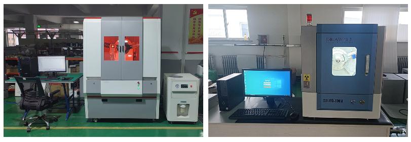
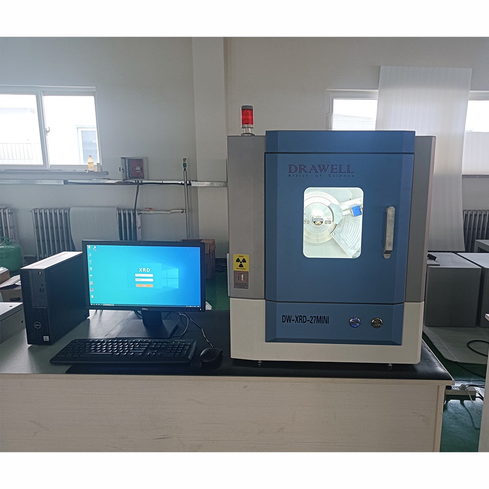
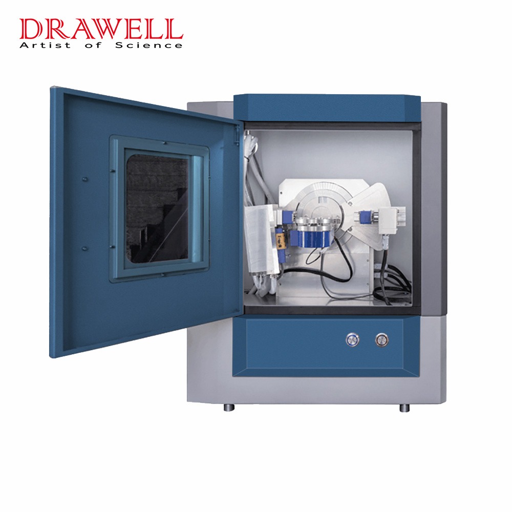
| Drawell | Flexible configurations, fast detectors, user-friendly interface, compact models (e.g., DW-XRD-27mini) | Routine lab analysis, polymer composites, academic research, industrial quality control |
A Final Word
XRD is a crucial tool for understanding polymers, whether they’re neatly ordered (crystalline) or more jumbled (amorphous), as well as complex materials like graphene oxide. It helps us pinpoint how much of a polymer is crystalline and reveals the precise atomic arrangements within those ordered sections. For amorphous materials, even without sharp peaks, XRD gives us clues about their internal structure and how it changes with heat or stress. And for graphene oxide, it’s key to seeing how layers are spaced and how well they’re dispersed in composites.
Getting good XRD results from polymers means paying close attention to sample preparation, managing any preferred orientation, and knowing how to handle materials with low crystallinity. Powerful software is also essential for accurate analysis. Ultimately, choosing the right XRD equipment from a reputable XRD manufacturer ensures you have the capabilities needed for your specific research. By mastering these points, researchers can fully leverage XRD to advance polymer science and create new materials.
Related Products Recommendation

Get Quote Here!
Latest Posts


What Next?
For more information, or to arrange an equipment demonstration, please visit our dedicated Product Homepage or contact one of our Product Managers.


