


JMHVS-1000AT PLUS Precision Digital Micro Vickers Hardness Tester
JMHVS-1000AT PLUS Precision Digital Micro Vickers Hardness Tester is a high-tech product of optical mechanical and electrical integration. The instrument has novel and beautiful shape, and it has good reliability, operability and intuitiveness. It is the upgrading product of micro vickers hardness tester.
Introduction of JMHVS-1000AT PLUS Micro Vickers Hardness Tester
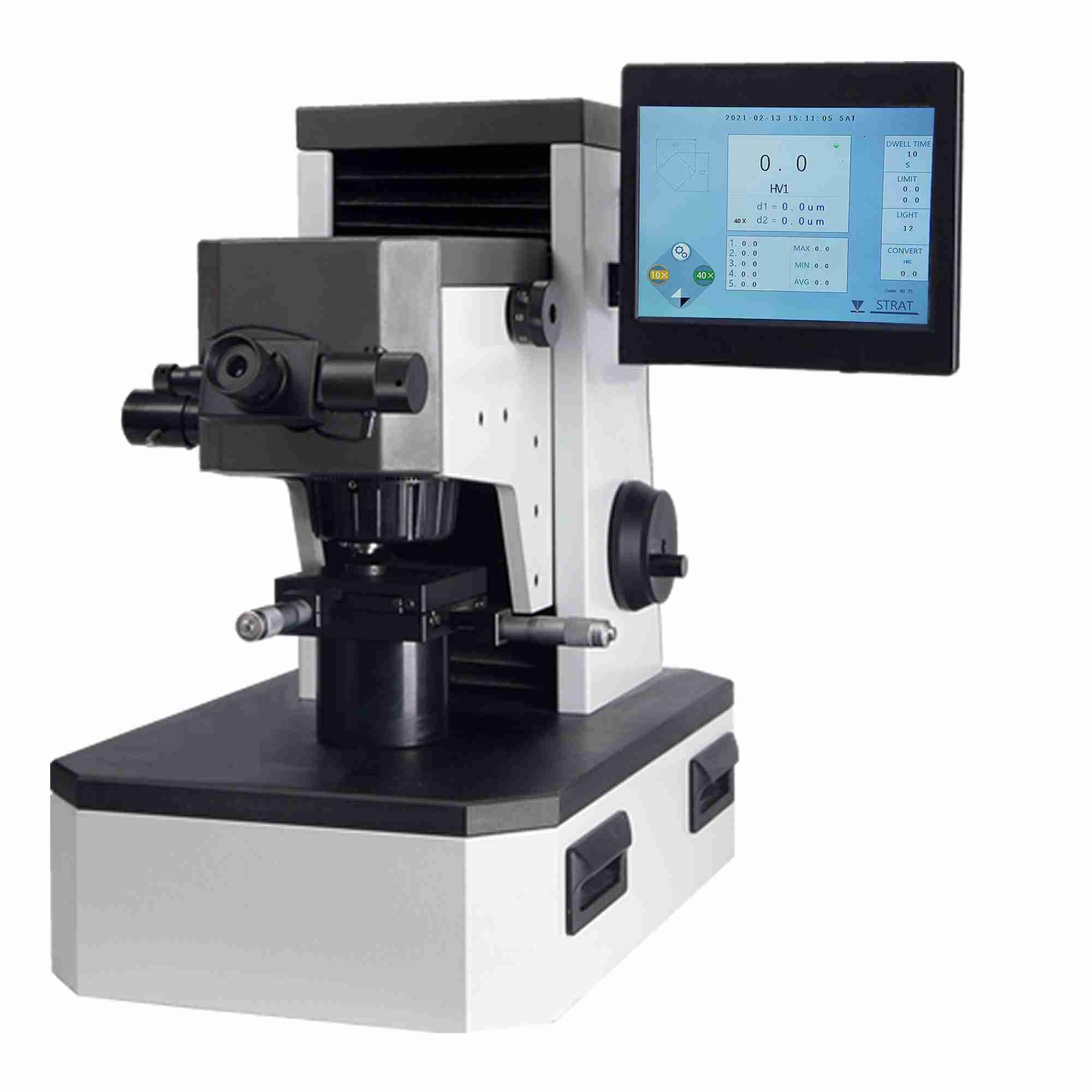
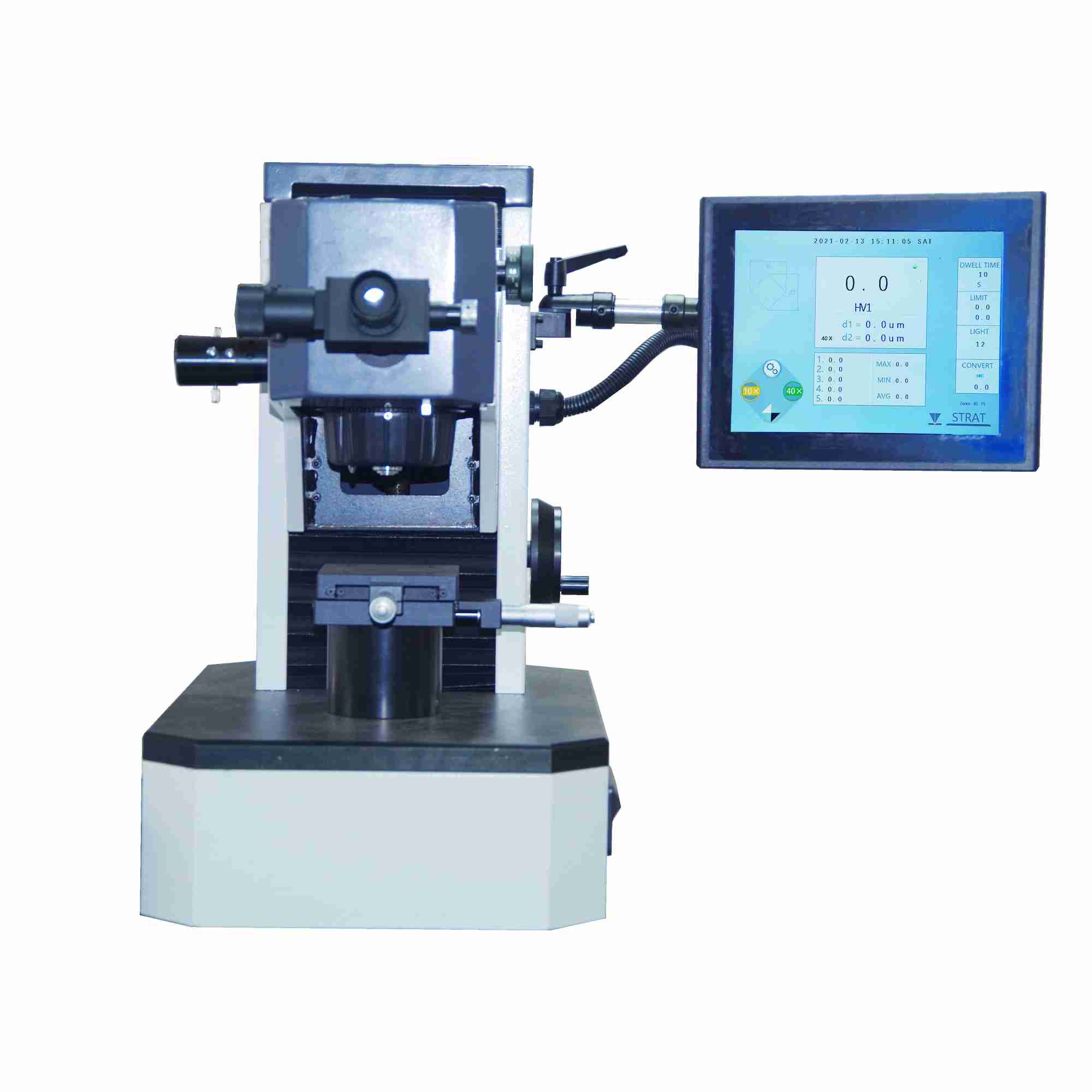
JMHVS-1000AT PLUS Precision Digital Micro Vickers Hardness Tester adopts computer software programming, high magnification optical measurement system, optical sensor and other technologies. Through touch screen input, it can adjust the strength and holding time of measuring light source, and provide various hardness value conversion tables for reference. On its 10 “color touch screen, it can display test method and test force; measure indentation length, hardness value and test force holding time. The number of measurements and the ability to type in the year, month, date, test results and data processing, etc., are output through the printer (optional). The hardness tester can be equipped with a photographic device, which can take pictures of the measured indentation and the metallographic structure of the material. It is suitable for measuring the microhardness of the micro and thin test pieces, the surface coating and other test pieces, and for measuring the microvickers hardness of the brittle materials such as glass, ceramics, agate and gemstone. It is an ideal hardness test instrument for the research and testing of scientific research institutions, enterprises and quality inspection departments.
Main Technical Parameters of JMHVS-1000AT PLUS Micro Vickers Hardness Tester
| Test force | 0.098、0.246、0.49、0.98、1.96、2.94、4.90、9.80N |
| Test force loading method | Automatic loading and uploading |
| Magnification of measuring eyepiece | 100X(Observe)400X(Test) |
| Test force dwell time | 0~60s(It can also be determined as needed.) |
| Minimum resolution of Microindentation | 0.02μm |
| Maximum height of specimen | 210mm |
| Maximum width of test piece | 320mm |
| Host weight | About 45kg |
| Power supply | AC220V/50HZ |
| Dimension:(L×W×H) | 490× 320×530mm |
Installation and Adjustment of JMHVS-1000AT PLUS Micro Vickers Hardness Tester
- Working conditions of hardness tester
- Within room temperature23±5℃;
- Horizontal placement on a firm basis;
- In a vibration free environment;
- No corrosive medium around;
- Indoor relative humidity is not more than 65%
- Unpacking and installation
- 1) Remove the outer packing box, take out the main packing box, remove the box cover and remove the main packing box;
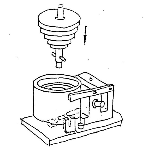
- 2) Separate the main body (1) from other accessories (Figure 1);
- 3) Take out the horizontal adjusting screw (19) from the accessory box and screw it on the bottom of the main body;
- 4) Pull out the eyepiece (6) and screw down the eyepiece tube. Remove the upper cover (7) in the direction of the arrow in the figure below. Remove the shockproof screw (Figure 2).;
- 5) Screw off the screws on the end cover of the weight shell, remove the lower end cover, take out the weight shaft and weight from the accessory box, and put six weights on the weight shaft from small to large. Wipe the weight shaft and weight before installation, so as not to stain them.
- 6) Hold the top of the weight shaft, put it into the weight housing, and turn the weight shaft to make its cross pin in the V-groove of the lever. (Fig. 3)
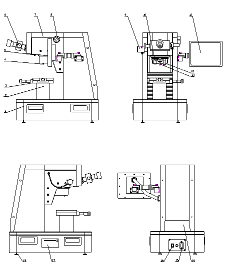
1. Body 2. Bench pedestal 3. XY test-bed 4. Indenter 5. Photographing and measuring transfer rod 6. Digital micrometer eyepiece 7. Upper cover 8. Test force change handwheel 9. Measuring light socket 10. 10XObjective lens 11. Display panel 12. 40XObjective lens 13. Indenter screw 14. Back cover 15. Power supply socket 16. Power switch 17. Panel printer(optional) 18. Horizontal adjusting screw
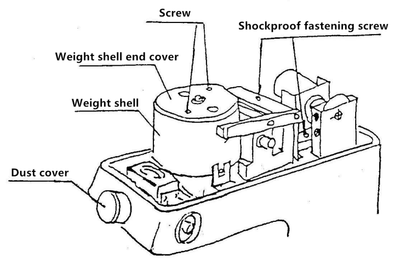
- 7) align the hole on the end cover with the weight shaft, make its shoulder match the weight housing hole, and tighten two m3 screws.
- 8) turn the test force change handwheel (9) to make the weight shell flexible up and down in the positioning groove, and cover the upper cover.
- 9) pull out the dust cover of the micrometer eyepiece, take out the micrometer eyepiece (6) from the accessory box, insert it into the hole, and insert it.The head is inserted into the left socket of the main body;
- 10) take out the test bench (3) from the accessory box, wipe the antirust oil with gasoline, and apply a proper amount of thin grease after drying;
- 11) install the cross test bench (3) on the test bench base (2) and fasten it with screws;
- 12) place the level gauge on the cross test bench, adjust the front and rear horizontal adjusting screws to make the blister centered.
Operation Panel and Function of JMHVS-1000AT PLUS Micro Vickers Hardness Tester
- Start to display the company’s trademark (as shown below)
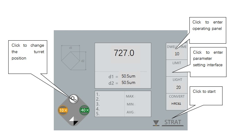
- Operation page (as shown below)
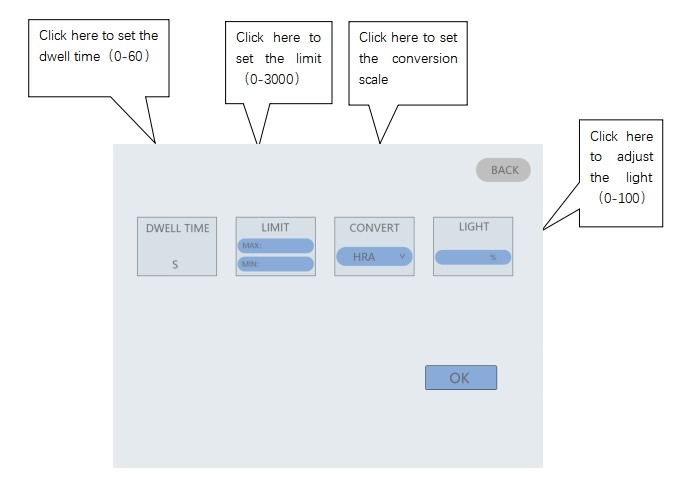
- Parameter setting page (as shown below)
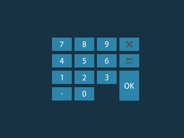
- Parameter input page (as shown below)
Use of JMHVS-1000AT PLUS Micro Vickers Hardness Tester
- The switch is located at the back side of the instrument, with power switch, fusible core base and power socket. Take out the power cord from the accessory box and connect it to the power supply.
- Turn on the power switch, the main screen will light up the start-up page, click the screen to enter the operation page, if you need to change the test force, please turn the test force change hand wheel to make the test force meet the selection requirements, the load force value should be consistent with the force value displayed on the main screen, if the force value display is inconsistent, it will cause the calculation formula error and affect the value, when you rotate the change hand wheel, you should be careful and slowly To prevent impact due to too fast speed.
- The zero position must be calibrated before starting each time. When the edges of the two lines are close to each other, the light transmission gap decreases gradually. When the two lines are in the critical state with or without light gap, i.e. when the zero position is reached, press and hold the eyepiece button for 3 seconds to clear and then the instrument will enter the standby state. At this time, you can put on the sample, focus and press the “start test” key to start the test.
- When the hardness tester is turned on, it will automatically turn the 40x objective (13) to the front position of the main body (optical system magnification 400X, measurement state), and 10x objective (11) is used for observation (optical system magnification 100x at this time).
- Place the standard test block or sample on the test bench (in the center of the objective lens), and the toilet head will descend. When the lower end of the objective lens is 1-3mm away from the test block or sample, the eye will approach the micrometer eyepiece for observation. In the eyepiece, the brightness will gradually increase with the slow decline of the head, indicating that the focus surface is coming, and the speed shall be slowed down until the surface of the test block or sample is observed in the eyepiece. The focus has been adjusted.
- If the image observed in the eyepiece is fuzzy, turn the lens at the front of the eyepiece (due to the difference of vision of each person) until it is clear. If the plane image of the test block observed in the eyepiece has local light and dark conditions, adjust the three adjustment screws on the light source device to make the light source in the center position. If the field of view is too bright or too dark, press the screen directly. Enter the parameters with the “Brightness” key on to adjust the brightness to a comfortable and clear state.
- If you want to observe a large field of view on the surface of the test block (if you need to find the preset position, etc.), change the 10x objective to the front of the main body, the focal plane of the 40x objective is slightly different from that of the 10x objective, you can adjust the head up and down to make its imaging clear, rotate the differential cylinder to move the X-Y platform, and then you can find the preset position. Note: if the hardness test is to be carried out, please turn the 40x objective lens to the front of the main body, and adjust the head to make its imaging clear, because the instrument adjusts the coordination between the components based on the 40x objective lens imaging.
- Press the “start test” key on the panel, and the instrument starts to load and maintain the load. After unloading, the 40x objective will automatically turn back to the measurement position, indicating that the test is completed and can be measured.
Note: if the surface of the sample is uneven or composed of multiple faces, care shall be taken to prevent the indenter from touching the sample when switching the indenter shaft.
- Observe the image of the indentation in the eyepiece. If the image of the indentation is not clear, adjust the head to make it clear. Because the indentation has depth, when the objective lens is magnified by 400X, the tiny depth still has an impact on the focal plane, which is normal.
- Move the reticle of the eyepiece to make it close gradually. When the inner side of the reticle approaches infinitely and the inner side of the reticle is in the critical state of no light gap, press and hold the eyepiece button for 3 seconds to clear. At this time, the value of D1: on the screen is zero, which is the zero position in the term.
- Turn the hand wheel on the right to separate the scribed line, and then move the drum on the left side of the eyepiece to move the scribed line on the left side. When the inner side of the scribed line on the left side is tangent to the intersection of the left shape of the indentation, then move the scribed line on the right side to make the inner side tangent to the intersection of the indentation shape. Press the measurement button on the eyepiece, and the measurement of the diagonal length D1 is completed. Move the eyepiece 90 °, and measure the diagonal with the above method. The line length D2, press the measurement button, at this time, the screen displays the indication of this measurement and the hardness indication converted. If you think there is an error in the measurement, you can repeat the above procedure to measure again.
- The second test can only be carried out after the first test (refers to the measurement after the test). According to the requirements of the verification regulation, the first indentation is not counted, so the hardness indication value of the second indentation is the first time recorded in the test times. At this time, the screen status shows the test times: once.
- When it is observed that the image of the indentation is too large in the eyepiece (60% of the eyepiece’s field of view is taken as the effective field of view), please reduce the test load, otherwise there is a certain error in the indicated value. For example, if the indentation observed in the eyepiece is small, the test load can be increased (it must be within the allowable range, otherwise it may break through the test piece), so as to improve the measurement accuracy.
Adjustment and Precautions of JMHVS-1000AT PLUS Micro Vickers Hardness Tester
- Before using the instrument, please read the operation manual carefully, understand the operation steps and precautions of the instrument in detail, and avoid instrument damage or personal safety accident due to improper use.
- When the instrument is installed and debugged, please carefully tear off the shockproof adhesive tape used to protect the indenter for transportation. Excessive force will damage the positioning accuracy of the indenter.
- It is strictly forbidden to dismantle the electrical, mechanical and optical mechanisms of the instrument by themselves. If they are disassembled without permission, accidents may occur.
- When the test force is being loaded or the test force is not removed, it is forbidden to rotate the rotary table, otherwise the instrument and diamond indenter will be damaged.
- Please do not apply the test force when the instrument is in the measuring state. If you accidentally press the “start test” key, only wait for the test force to be applied and the objective will automatically rotate before measuring.
- Diamond indenter
- ① Diamond indenter (4) and indenter shaft are very important parts of the instrument, so be very careful not to touch the indenter during operation.
- ② In order to ensure the test accuracy, the indenter shall be clean. When it is stained with oil or dust, it can be dipped with alcohol (for industrial use) or ether with degreasing cotton, and it can be wiped carefully at the top of the indenter.
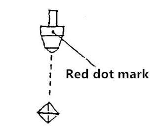
- ③ There is a red mark at the outer circle of the indenter. For example, when the indenter is removed and reinstalled, the red point shall be in front of the indenter, and the intersection of the diagonal of the indenter and the red point shall form a line. (see chart 17)
- Micrometer eyepiece
- ① Due to the parallax of each person, the reticle in the field of view of the observation eyepiece may be blurred. Therefore, when the observer changes people, the eyepiece lens should be rotated slightly to make the reticle in the field of view clear.
- ② The micro eyepiece is in the eyepiece tube. When measuring the diagonal of the indentation and rotating the eyepiece at 90 °, pay attention to that the micro eyepiece is close to the eyepiece tube without any gap, otherwise it will affect the measurement accuracy.
- Microscope light source
The central position of the light source will directly affect the image quality of the indentation. If the image quality is fuzzy or the brightness is uneven, adjust the center. Carefully adjust the three screws so that the center of the bulb is in line with the center of the light source.
- Sample
- ① The sample surface must be clean. If the surface is stained with grease and dirt, the accuracy of measurement will be affected. When cleaning the sample, wipe it with alcohol or ether.
- ② When the sample is thin wire, thin sheet or small piece, the thin wire clamping table, thin sheet clamping table and flat mouth clamping table can be used respectively: the small test piece must be made into the inlay and polished before the test.The surface roughness of the test piece is not more than 0.05 μ M,The surface roughness of bearing surface shall not be greater than 0.8 μ M.
- Microphotograph
- ① The instrument can be equipped with a microphotograph and can take photos of the material test results. When shooting is needed, remove the photography cover plate on the upper cover and screw the camera interface in the accessory box into the eyepiece base thread.
- ② Take off the standard lens of the camera, and align the camera interface with the lens hole to make the snap ring snap.
- ③ Observe the surface in a micrometer. When the image is clear, pull out the photogrammetric transfer lever (5) on the left side of the main body. This time path changes to shooting state.
- ④ Observe the surface of the sample in the eyepiece of the camera. If it is not clear, fine adjust the vision adjusting circle or the head focus to make the image clear.
- ⑤ Press the shutter to capture the imaging surface.
Accessories(Packing list) of JMHVS-1000AT PLUS Micro Vickers Hardness Tester
- Host(Including one micro Vickers indenter, one 10x and one 40x objective lens)
- Test-bed、weight、Microscope accessory box
| Weight shaft | 1 |
| Weight | 6 |
| XY test-bed | 1 |
| Slice holder | 1 |
| Flat clamping table | 1 |
| Filament holder | 1 |
| Screwdriver | 2 |
| Horizontal adjusting screw | 4 |
| Power cord | 1 |
| 10x Digital micrometer eyepiece | 1 |
| Micro Vickers test block | 2 |
| Level | 1 |
| Spare core | 2 |
- Micro image analysis system (supplied according to the contract)
| Image analysis software | 1 |
| CCD Camera | 1 |
| Optical tie rod | 1 |
| Computer(according to user requirements) | 1 |
| Product certificate | 1 |
| Manual book | 1 |


