
JMHVS-1000-XYZ Full Automatic Micro Vickers Hardness Tester
The “Drawell” automatic Vickers hardness image measurement system integrates the latest professional technologies such as optical imaging, mechanical displacement, electronic control, digital imaging, image analysis, computer processing, etc. it controls the micro Vickers hardness tester and automatic stage through the computer host, and digitizes the hardness indentation image on the computer screen, and then through automatic reading, image analysis, computer processing, etc By means of manual reading, the microhardness, depth of hardened layer, thickness of film and distance between two points of metal and some non-metallic materials, various films and coatings can be accurately measured. It can also photograph metal surface morphology and print at fixed rate. This system breaks through the traditional way of hardness test and realizes the automatic, high precision and high repeatability hardness test. It is an important equipment for material analysis.
Functional Features of JMHVS-1000-XYZ Micro Vickers Hardness Tester
- The light source can be adjusted by pressing the key
- Brand new design, nose down pressing structure (the first in China)
- The test force holding time can be preset
- The machine adopts unique indentation measurement conversion and micrometer eyepiece one-time measurement reading mechanism
- Software built in hardness conversion table
- It is easy to use and has high measurement accuracy
- The hardness tester can also be equipped with photographic device according to the special requirements of users
- Automatic loading and unloading control
- Double optical channel (eyepiece and CCD camera channel), can be connected with computer control system
- The selection of micro Vickers and Knoop hardness scales
- The hardness value tested can be calculated and displayed automatically
- Automatic switching indenter and objective lens (automatic turret)
- The automatic positioning of test points is accurate
Technical Parameters of JMHVS-1000-XYZ Micro Vickers Hardness Tester
| Model | JMHVS-1000-XYZ |
| Controlling system | Precision step controlling system |
| Platform | High precision linear slide guide lifting platform |
| Test force | 10gf、25gf、50gf、100gf、200gf、300gf、500gf、1kgf |
| 0.098N、0.245N、0.49N、0.98N、1.96N、2.94N、4.9N、9.8N | |
| Executive standard | GBT4340、ISO 6507、ASTM_E92 |
| Minimum measuring unit | 0.01µm |
| Hardness measuring range | 5-3000HV |
| Loading method | Automatic (loading、holding、uploading) |
| Magnification | 100X(Test) |
| 400X(Observe) | |
| Indenter and objective lens switch | automatic |
| Conversion scale | HR、HB、HV |
| Dwell time | 5-60s |
| Manual X-Y table | size:100*100mm maximum route:25*25mm |
| Maximum sample height | 180mm |
| Distance from the center of indenter to the body | 136mm |
| Power supply | AC220V+5%,50-60Hz |
| Dimensions | 490*350*540mm |
| Machine net weight | About 60kg |
Hardness Measuring System of JMHVS-1000-XYZ Micro Vickers Hardness Tester
Basic Functions of Hardness Measuring System
- The automatic recognition ability of indentation image is leading, and the detection efficiency, stability and accuracy of detection results are high.
- Two kinds of calibration: optical calibration, (manual / automatic) hardness block calibration. The hardness block supports multiple averaging, arbitrary multiple standard blocks, subsection calibration and optimal measurement.
- Besides automatic measurement, there are three kinds of manual measurement: four side measurement, diagonal measurement and four point measurement(Four vertex selection order can be arbitrary).
- Support three types of indentation marking: “Rectangle”, “Red Cross” and “circle”.
- When measuring manually, it has the function of magnifying glass, which is convenient to find the position of indentation vertex;The unique keyboard shortcut function can quickly move the selected vertex to make the measurement operation more efficient.
- The pixel distance and physical distance of indentation diagonal are provided, and the HV / HK value under current load is calculated in real time.
- Automatic switch the turret (Objective lens、indenter).
- 1.3 million digital cameras that display indentation video on a computer. It can capture and store images.
- Real time display and update the current status of the hardness tester: current indenter / objective, dwell time, loading force, etc。
- The distance between two points can be measured manually, and multiple groups of distances can be displayed on the video or image at the same time.
- When the resolution, objective and load are different, the software will automatically select the best calibration coefficient.
- All test point information can be identified individually or according to customer requirements. The test point identification information will be displayed in the test value sequence table and indentation diagram for easy query. This function is very important for subsequent analysis and processing.
- Refer to GB, DIN, ISO, ASTM and other Hardness Conversion standards,can satisfy the conversion between hardness values such as:Vickers HV、Knoop HK;Rockwell: HRC、HRA、HRB、HRD、HRE、HRF、HRG、HRK;Superficial Rockwell:HR15N、HR30N、HR45N、HR15T、HR30T、HR45T;Brinell HBS、Brinell HBW etc.
- When measuring the hardened layer path sequence, there are various flexible initialization modes to automatically save and import the previous path sequence; the measurement path can also be saved arbitrarily for re loading.
- According to the measurement results of path sequence, the corresponding hardened layer depth value and hardness change curve are automatically generated.
- Multiple analysis modes can be selected for the measurement data; all results can be set into graphic reports.
- The report content and format can be set flexibly, and word and EXCEL documents can be generated automatically.
- Password and management authority can be set: ordinary operators can only measure hardness according to the set settings.
- The built-in conversion tool of each standard hardness value can automatically convert the measured hardness value according to the table and list it in the result table.
Advanced Features of Hardness Measuring System
- Path planning function. As an extension of distance measurement function, 17 modes of path to be measured are accurately planned by clicking the image with the mouse.
- Free point selection: select any position of the image to become the path to be measured.
- Any direction: select any starting point and line segment in any direction.
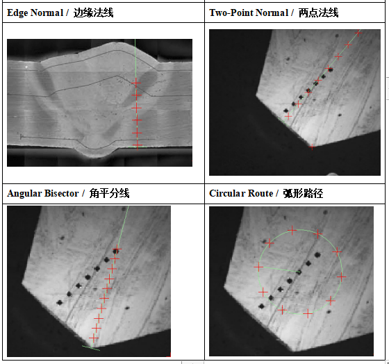
- Edge normal: click near the edge to generate normal line segment automatically.
- Two point normals: select the two ends of the edge to generate the center normal line segment.
- Angle bisector: three points construct angle and generate angle bisector line segment.
- Circular path: the center / radius of the circle is determined by two points, and the path is generated in time.
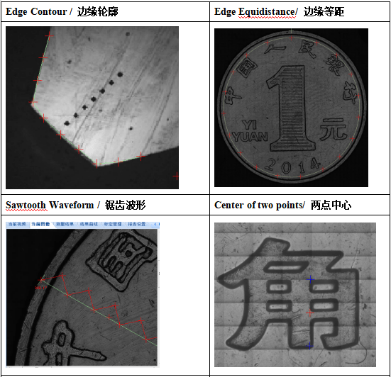
- Edge contour: click near the edge to automatically generate a path along the edge.
- Edge equidistant: along the edge, select the distance to generate equidistant line segments.
- Sawtooth waveform: period, tooth height and tooth symmetry can be set quantitatively.
- Two point center: select two points on the image and generate the midpoint as the path to be measured.
- Line: select any starting point, any direction of straight line segment, middle variable distance.
- Multiline: multiline path points.
- Serrated: serrated multiline。
- Interpolation: insert a fixed number / distance of path points between two points.
- Matrix: path point of rectangular array.
- Wheels: wheel path points.
- Ring: ring path point.
- The function of indenter/lens offset calibration is provided to eliminate the mechanical deviation between indenter and lens and correct the overall error of the system, so as to improve the accuracy of hardness test results.
- Edge scan function. Through the movement of XY automatic platform, the edge of the specified object can be scanned and the contour of the object edge can be drawn.
- Panoramic mosaic function. Through the “panoramic scanning” function, you can get the panoramic image of the specified range, and do any path planning on the image.
- Regional model & continuous test and continuous play function. For multiple indentations in the same field of vision, the region mode can be selected, and only the indentations within the set range are considered in each measurement. When the area mode is turned on during continuous test, the test interruption caused by multiple indentation in the same field of vision can be avoided. Surface correction function.
- Surface correction function. According to table 1 and table 2 of ASTM E384 standard, the test and correction requirements of ball, rod and other curved parts are provided.
- Angle correction function. It can eliminate the angle deviation between the platform and the camera and improve the positioning accuracy of the platform by automatically correcting the angle.
- Multi sample panoramic splicing function. Panoramic mosaics can be performed on multiple samples at the same time, and then path planning can be done on these panoramic images. Finally, complete the continuous test.
- Automatic brightness function. The surface of the sample can be automatically adjusted to the best state. The appropriate brightness can better distinguish the indentation from the surrounding, and help to more accurately identify the indentation vertex.
- According to the measurement results of Vickers and Knoop, the effectiveness alarm function is introduced for the suspicious shape indentation that does not meet the ASTM E384 standard. (Optional)
- 3D analysis function and optional module “planar hardness distribution 3D map” are very effective means to analyze the hardness distribution on the surface of heat treated parts. (Optional)
- Built in pre denture template can greatly save the setting time of complex and time-consuming test points, especially the setting of tooth flank test points. All standard presets such as HK30 and hk0.5 can be implemented in one device. The corresponding reports are also stored. (Optional)
- More detailed and accurate hardness distribution can be obtained by generating test points with minimum interval. (Optional)
Main Technical Parameters of Software of Hardness Measuring System
| Automatic platform | ultra precision grinding and other aerospace level processing technology.Superior sealing performance ensures the stability of recovery accuracy after long-term use. |
| Platform dimensions | 255mmx205mm/310mmx255mm (Can be selected according to customer needs) |
| Maximum displacement in XY direction | 60x55mm / 110x110mm (optional according to customer demand), minimum step 0.625 μ M |
| Recovery accuracy | One way full journey≤10µm, Whole scan≤20µm |
| Camera | German high speed HD camera. |
Host standard configuration of JMHVS-1000-XYZ Micro Vickers Hardness Tester
| Name | Quantity | Name | Quantity |
| XY table | 1 | Wafer holder | 1 |
| Flat clamping table | 1 | Threadlet holder | 1 |
| bolt driver | 2 | Horizontal adjusting screw | 4 |
| 10x micrometer eyepiece | 1 | Micro Vickers hardness block | 2 |
| Level | 1 | Spare fuse | 2 |
| Manual book | 1 | Product certificate | 1 |
Main Configuration of Hardness Measurement System
| No | Model and specification | Quantity |
| 1 | Image analysis and measurement software (dongle and CD) | 1 |
| 2 | Imported HD camera | 1 |
| 3 | Standard route: XY automatic platform (route: about 60x55mm)Optional route: about 110x110mm (optional according to customer demand) | 1 |
| 4 | XY automatic platform control system | 1 |
| 5 | 1X C standard interface | 1 |
| 6 | data line | 1 |
| 7 | Computer | 1 |


